
CIRCUIT THEORY & DESCRIPTION
The theory is quite simple, if you remember how to work with phasors in the complex plane.
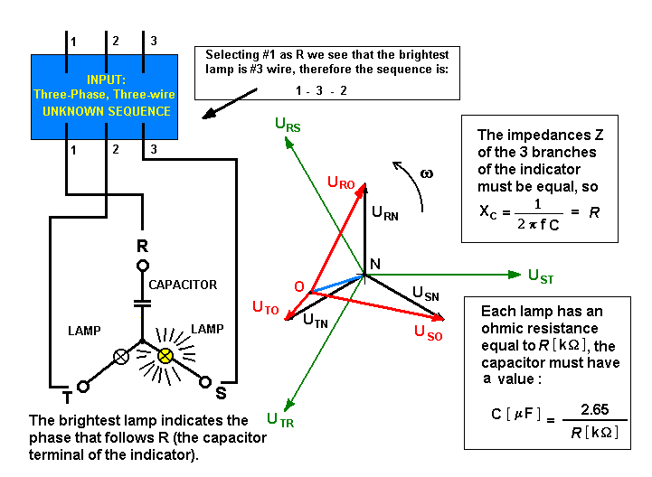
We are connecting three reactances of the same value in a three-star system arrangement, without neutral wire. If all reactances are of the resistive type the system will be equilibrated and the neutral point will have no voltage. But the capacitor introduces a phase displacement (the current leads 90 degrees over the phase voltage), thus the system will no longer be equilibrated and the star's neutral point O now has certain voltage ( Von).
As line voltage is constant, phase voltages will rearrange in order to give the neutral point voltage Von observed.
The mathematical resolution for a 3x220volt 3 phase - 3 wire system is:
UL = line voltage (220 v of the 3x220v star system): Urs; Ust; Utr
UF = phase voltage ( UL/sqr(3) = 127 volt): Urn, Usn, Utn
Zr = Xc ; Zs = R ; Zt = R indicator's branch impedance
Yr = 1/Zr ; Ys = 1/Zs ; Yt = 1/Zt branch admittance
It may be shown that the neutral point O of the indicator star connection will be submitted to a voltage Uon in relation to the neutral wire N of the mains supply:
Uon = ( Urn .Yr + Usn . Ys + Utn . Yt ) / ( Yr + Ys + Yt )
therefore, the new displaced phase voltages due to neutral point O displacement referred to N measured in the indicator will be:
branch phase voltage:
Uro = Urn - Uon
Uso = Usn - Uon
Uto = Utn - Uon
branch phase current (= line current)
Ir = Uro . Yr
Is = Uso . Ys
It = Uto . Yt
now we will verify that due to the neutral point displacement :
Uro + Uso + Uto = - 3 . Uon
and as line voltage is constant:
Urs = Uro - Uso
Ust = Uso - Uto
Uto = Uto - Uro
...................................
Doing some math and remembering that we are dealing with phasors in a complex plane we'll arrive to:
UL = 220 v ; Uf = 127 v
Uro = 170 v ( indicator's capacitor branch )
Uso = 190 v (branch following the capacitor branch - in sequence)
Uto = 51 v (branch that follows the branch with the illuminated lamp)
As we can see the branch with the greatest voltage (assuming the indicator was connected in the right sequence RST) is the branch with 190 volts, i.e.: that lamp will shine brighter than the one submitted to 51 volts. Therefore the phase that follows the capacitor branch is the one connected to the terminal with the brightest lamp.
Also we may see why we must use lamps with a rated voltage equal to the line voltage, i.e.: 220v ----> 190 volts.
If we use a 127v lamp... well, the indicator will work, but you don't want to buy new bulbs each time you use the gadget, will you? (lol)
CONSTRUCTION TIPS
You'll need 2 incandescent bulbs with a rated voltage equal to the line voltage, i.e.: in a 3x380v system - 380v rating; in a 3x220v system - 220v rating. Also a capacitor with a working AC rating equal to twice the line voltage (to be on the safe side).
All three elements are connected in star connection but without a neutral wire!
Measure the ohmic resistance R of the bulbs. The condition to fulfill is that the three reactances must be equal, so the reactive capacitance should be:
XC = R and Xc = 1 / (2. pi . f . C ) from which :
C = 1 / ( 2. pi . f . R)
with R in kohms, C in microfarads and f = 60 Hz , we have the capacitor's value:
C [uF] = 1 / ( 0.12 pi R ) = 2.65 / R [kohm]
To test the Indicator select one phase (it doesn't matter which one) and then connect the reference terminal of the indicator (the one with the capacitor), connect the other indicator's terminals. You'll see there's a lamp that shines brighter..., the phase connected to this branch is the phase that follows the one connected to the capacitor terminal (reference branch).